Monday 17 January 2022

failure of cutting tool

  failure of cutting tool


Whenever the tool is not performing the machining operation satisfactorily, then there is a failure of cutting tool.

The following draw backs are observed if the tool failure occurs.

1.      The tool ceases to produce the work-piece according to the required dimensions.

2.      The tool gets overheated.

3.      Excessive surface roughness is observed.

4.      Forces and power consumption increases.

5.      Sometimes the burnishing brand will appear on the work piece.

6.      Produces vibrations during machining.

The parameters used for measurement of satisfactoriness of machining is

1. Surface finish produced on work piece

§  At the beginning of machining operation it is found that excellence and mirror like finish is produced on work piece.

§  After sometimes when the lines are produced on machined surface, it is assumed that surface finish is reduced and tool is failed.

2. Forces induce during machining:

§  By connecting dynamo meter to the work table, the forces in machining will be measured online.

§  Whenever the increase in forces is taking place it is assumed that tool has been failed.

3. Power consumption:

§  By connecting Ammeter to the input of electrical motor, the current drawn by motor will be measured online.

§  Whenever the increase in current drawn by motor is greater it is assumed that tool has been failed.

4. Temperature of chip:

§  The temperature of chip can measured by observing the color of chip formed.

§  During normal satisfactory machining conditions the color of chip is light Blue or metallic color.

§  When the machining is done with failure tool, because of higher heat generation the color of chip is turned to black or burnt color.

§  From the above whenever the color of chip is observed to be black or burnt color, tool is assumed to be failed.

§  During machining of high carbon work pieces, whenever white colored gases are observed, it is assumed that tool is failed.

Modes of tools failure:

1.      Failure through plastic deformation

2.      Failure through mechanical breakage

3.      Failure through mechanical gradual wear

1. Plastic Deformation Failure:

Whenever the tip of tool is experiencing temperature greater than hot hardness temperature of tool material, it is losing its hardness considerably and the tip of tool is deforming plastically called as plastic deformation failure of the tool.
Reasons for plastic deformation failure:

1.      Wrong selection of tool material.

2.      Wrong selection of process parameters.

2. Mechanical Breakage Failure:

A cutting tool gets broken due to the following factors:

1.      Large cutting force.

2.      By developing fatigue cracks under chatter conditions.

3.      Weak tool materials.

4.      High temperature and high stress.

In this also failure duration is repeatable.
Therefore it is also considered as abnormal failure of tool.

3. Mechanical Gradual wear failure:

During machining operation, the tool is wearing out and slowly and whenever the wear become considerable, it can’t perform the machining satisfactory called as gradual wear failure.
The gradual wear takes place due to
1. Crater wear and
2. Flank wear


Crater wear:

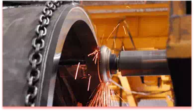
§  The major tendency for wear is due to the abrasion between the chip and the face of the tool, a short distance from the cutting edge.

§  The crater  (a shallow spherical depression present on surface) is formed on the surface of the tool by the nation of chip particles flowing over it because of very high temperature.

§  When Cratering becomes excessive, the cutting edge may break from the tool.

§  Cratering is commonly observed while machining ductile materials, which produce continuous chips.

Reasons for crater wear:

§  Presence of friction between chip – tool interference.

§  Abrasive action of microchips present at chip – tool interference.

§  Abrasive action of fragments of built up edge present at chip-tool interface diffusion wear.

Flank wear:
Wear taking place on flank face of tool is called as flank wear.

Reasons for flank wear:

1.      Presence of friction at tool interface.

2.      Abrasion action of microchips present at tool work interface.

3.      Diffusion wear.

Saturday 15 January 2022

Covid treatment for cars????

Did you know about the covid 19 treatment for your cars !!!!!!


 Yes, you are confused, I was like that at the time


 I am so happy to share my new experience after a long day


 I recently went to a car service center where I was amazed by an incident where the vehicle corona prevention system

That means technically they are do sanitation our cars by using sanitizers 

Completely they are doing sanitation our cars  in case any covid virus in our car 99

%this process will kill the virus this is new experience for me if u knew already do the comments 

Monday 10 January 2022

How to improve your car visibility.


How to improve your car visibility


   Every one facing same problem in our car at rainy session visibility plur its big problem even this is the reason for  70% accident  below i mention some tips how to improve your car visibility if my tip helps you kindly follow my blog 

Technical world


Rain-X – coating your windows with Rain-X or another water repellent coating 

meant for glass will increase many fold your vision when it is raining and make your 

windshield wipers much more effective. Water will literally fly off your windshield. 

As an alternative to a dedicated water repellent glass coating, many use a sealant on 

their glass. This has nearly the same effect, but has been known to cause the window 

to fog in some weather conditions. It is not recommended that you wax your glass as 

wax is not as transparent (a/k/a “optically true”) as sealants.

Monday 3 January 2022

Anti lock breaking system (ABS)

 Anti-Braking System  is a safety system that allows the wheels on a motor vehicle to continue interacting tractively with the road surface as directed by driver steering inputs while braking, preventing the wheels from locking up (that is, ceasing rotation) and therefore


Abs break by technical world

 avoiding skidding.  A skidding wheel (where the tire contact patch is sliding relative to the road) has less traction than a non-skidding wheel. If you have been stuck on ice, you know that if your wheels are spinning you have no traction. This is because the contact patch is sliding relative to the ice. By keeping the wheels from skidding while you slow down, anti-lock brakes benefit you in two ways: You’ll stop faster, and you’ll be able to steer while you stop.

There are four main components to an ABS system:

a)    Speed sensors

      b)  Pump

      c)  Valves

      d)  Controller

Speed Sensors– The anti-lock braking system needs some way of knowing when a wheel is about to lock up. The speed sensors, which are located at each wheel, or in some cases in the differential, provide this information.

Valves– There is a valve in the brake line of each brake controlled by the ABS. On some systems, the valve has three positions:

· In position one, the valve is open; pressure from the master cylinder is passed right through to the brake.

· In position two, the valve blocks the line, isolating that brake from the master cylinder. This prevents the pressure from rising further should the driver push the brake pedal harder.

·   In position three, the valve releases some of the pressure from the brake.

Pump– Since the valve is able to release pressure from the brakes, there has to be some way to put that pressure back. That is what the pump does; when a valve reduces the pressure in a line, the pump is there to get the pressure back up.

Controller– The controller is a computer in the car. It watches the speed sensors and controls the valves.

Rant: In Free(!)fall | Pedantic Perspective

An ABS generally offers improved vehicle control and decreases stopping distances on dry and slippery surfaces for many drivers; however, on loose surfaces like gravel or snow-covered pavement, an ABS can significantly increase braking distance, although still improving vehicle control.

Friday 31 December 2021

Stainless Steel and its type


Stainless Steel is defined as that steel which when correctly heat treated and finished, resists oxidation and corrosive attack from most-corrosive media. The different types of stainless steels are as follows:

1. Martensitic stainless steel. The chromium steels containing 12 to 14% chromium and 0.12 to 0.35% carbon is called martensitic stainless steel, as they possess martensitic structure. These steels are magnetic and may be hardened by suitable heat treatment and the hardness obtainable depends upon the carbon content. These steels can be easily welded and machined.

2. Ferritic stainless steel. The steels containing greater amount of chromium (from 16 to 18%) and about 0.12% carbon are called ferritic stainless steels. These steels have better corrosion resistant property than martensitic stainless steels.

3. Austenitic stainless steel. The steel containing high content of both chromium and nickel are called austenitic stainless steels. The most widely used steel contains 18% chromium and 8% nickel. Such a steel is commonly known as 18/8 steel. These steels are non-magnetic and possesses greatest resistance to corrosion and good mechanical properties at elevated temperature.

Thursday 30 December 2021

governing of I.C. engines by moses dhilipkumar

 The process of providing any arrangement, which will keep the engine speed constant (according to the changing load conditions) is known as governing of I.C. engines. Though there are many methods for the governing of I.C. engines, yet the following are important :

1. Hit and miss governing. In this system of governing, whenever the engine starts running at higher speed (due to decreased load), some explosions are omitted or missed. This is done with the help of a centrifugal governor. This method of governing is widely used for I. C. engines of smaller capacity or gas engines.

2. Qualitative governing. In this system of governing, a control valve is fitted in the fuel delivery pipe, which controls the quantity of fuel to be mixed in the charge. The movement of control valve is regulated by the centrifugal governor through rack and pinion arrangement.

3. Quantitative governing. In this system of goverliing, the quality of charge (i.e. air-fuel ratio of the mixture) is kept constant. But the quantity of mixture supplied to the engine cylinder is  varied by means of a throttle valve which is regulated by the centrifugal governor through rack and pinion arrangement.

4. Combination system of governing. In this system of governing, the qualitative and quantitative methods of governing are combined together.

Wednesday 29 December 2021

Black exhaust smoke


 BLACK EXHAUST SMOKE


Diagnosis: Not normal

Black exhaust smoke can appear when the vehicle is burning too much fuel. This could be caused by a clogged air filter, malfunctioning fuel injection system, a blocked manifold, or a variety of other issues. A clogged air filter won't hurt your gas mileage thanks to today’s automotive technology, says Consumer Reports, but you’ll pay for it with poor performance. Have your vehicle checked out by a technician to see why your vehicle is burning more fuel than usual.