Amazon is back with a discount reserved just for its Prime subscribers. The finest bargains and offers will be available during the "Prime Day" event, which will take place on July 23 and 24. And this time, discounts are pouring in like rain!
Over 400 new products will be introduced during the two-day mega event, along with some intriguing offers and discounts. Additionally, holders of ICICI and SBI credit/debit cards receive an extra 10% in discounts.
The opportunity to purchase the most eagerly awaited goods will be provided by the approaching Prime Day sale. The two-day spectacular Amazon Prime Day Sale has leading brands including Samsung, Fastrack, Boat, Adidas, Wakefit, and many more. Consequently, all of the items on the website that you were interested in
Students can learn the principles of designing the most often used components, elements, and units of diverse machines by taking the Topics in Machine Design course. The machine as a whole as well as each of its individual components must be developed since little machine parts when put together create large machines.
The following are some ways that designers benefit from understanding machine design:
1) To choose the right materials and the best shapes,
2) Calculate the dimensions using the machine loads and the material's strength.
3) Describe how the designed machine component or the entire machine will be manufactured, including the manufacturing process.
Machine design is the application of mathematics, kinematics, statics, dynamics, engineering materials, metals technology, mechanical drawing, and mechanics of materials.
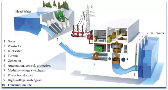
Dam is built through the river and water is stored, from that hydroelectric power plant operates to develop the potential energy. From the stored water the potential energy is converted into the kinetic energy. With the help of the penstock pipe the water must flows through it as it generates the energy. In the water turbine the developed kinetic energy must be converted into the mechanical energy. Here, to the electric generator the turbine is coupled. In the turbine at the shaft the mechanical energy is converted into the electrical energy with the help of generator. Due to gravity it provides the force which allows the water to flow, in this water the stored energy is known as gravitational potential energy.
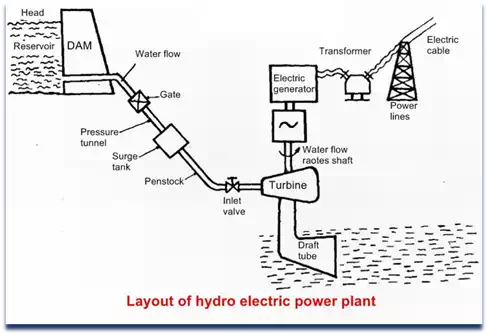
Layouts of hydroelectric power plant:
Dam
Water reservoir
Gate
Spillway
Surge tank
Pressure tunnel
Penstock
Water turbine
Draft tube
Tail race level
Power house
Dam:
The main purpose of the dam is to store the water and to control the outgoing run of water. All the incoming water is stored in the dam. The water head is increased with the help of the dam, which is essential when an enough head is available.#Hydro electric powerplant
Water reservoir:
During rainy season in a reservoir water is collected from the watershed and stored behind the dam. At the time of rainy season, water from rivers is stockpiled behind a dam. Nonstop accessibility of water is an elementary requirement for a hydroelectric power plant. In the reservoir the level of surface water is called head water level. The available water head for power generation hang on the reservoir height
Gate:
The main purpose of the gate is used to control the flow of water from dam.
Spillway:
High amount of water in the reservoir leads to the damage of the reservoir so that a stable state of water is maintained in the dam. During rainy seasons spillways are provided to avoid the water flow and to release the water outside. So the risk factor must be reduced and the water level in the dam also comes down. The excess water present in the storage area is allowed outside by using the spillways.
Surge Tank:
It is a small tank or a reservoir in which the water level falls or rises due to sudden pressure change. Due to sudden increment of the pressure in the penstock pipe we can notice the sudden backflow of the water. On the turbine the load must be decreased. The rapid rise of pressure in the penstock pipe is called as water hammer. The surge tank is situated between the turbine and dam to serve the water at the time of need.
By reducing the gap between the turbine and the dam is in the way of reducing the water hammer effect also. It functions as a source tank to the turbine, while the water in the pipe is enhanced during amplified load conditions, as storage tank when the water is slow down during compact load conditions.
Pressure tunnel
By using the pressure tunnel the water passes from the reservoir to the surge tank.
Penstock
The main aim of the penstock is to bring the water from the dam to the hydraulic turbine. The pipes are made up of reinforced concrete or steel. In the dam at low level the turbines are to be installed. At the inlet, gate is delivers to the penstocks in order to close the water supply. To control the water flow rate it delivers gate valve at the inlet to totally close by the water supply. It has a regulator valve to switch the water flow rate into the turbine
Water turbine
The water turbine is also known as hydraulic turbine. The turbine converts the water energy into the mechanical energy. On the turbine shaft the available mechanical energy, this is joined to the shaft for the electrical generator which produces the electrical energy. The water present in the turbine blade is discharged through the draft tube. The prime motivators which are in mutual use are Kaplan turbine, Pelton wheel and Francis turbine
Draft tube
Draft tube is linked to the exit of the turbine. It exchanges the kinetic energy offered in the water into pressure energy in the differing portion. It retains a pressure of impartial in the atmospheric at exist of the draft tube to run the water into a tail race. From the tail race water is released for irrigation purposes.
Tail race level
Tail race is a water path to lead the water exiting from the turbine to the canal or river. In the tail race the water detained is called Tailrace water level
Power house
The power houses provide accommodations the generator, transformer and water turbine and along with control room.
If the water flows through the turbine, there water turns the turbine shaft, and it is joined to the electric generator.
A rotating electromagnet is attached to generator it called a rotor and a motionless part called as a stator.
A magnetic field that produces with the help of rotor and an electric charge is produced in the stator.
The charge is transferred as electricity. The step up transformer raises the voltage of the current coming from the stator. Through the power lines the electricity is distributed
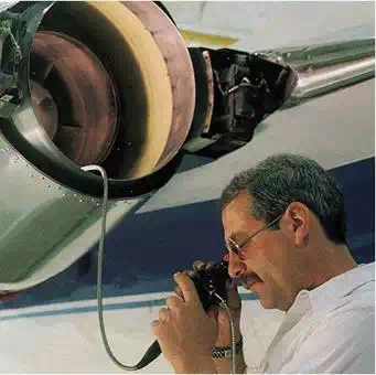
In casting process, first few castings will be inspected dimensionally and the pattern is qualified afterwards, only few random inspection will be done. Every casting must be inspected for finding out the defects in casting process.
Different methods of inspection for finding out defects in casting process are discussed below
1. Visual Inspection
2. Hydrostatic Pressure Test
3. Magnetic Particle Inspection
4. Radiographic Examination
5. Ultrasonic inspection
6. Dye Penetrant Inspection
7. Coin Testing
1. Visual Inspection
Common defects such as surface roughness, obvious shifts, omission of cores and surface cracks can be detected by a visual inspection of the casting. (#casting )Cracks may also be detected by hitting the casting with a mallet and listening to the quality of the tone produced.
#casting testing
2. Hydrostatic Pressure Test
§ The Hydrostatic pressure test is conducted on a casting to be used as a pressure vessel.
§ In this test, first all the flanges and ports are blocked.
§ Then the casting is filled with water, oil or compressed air, Thereafter, the casting is submerged in a soap solution when any leak will be evident by the bubbles that come out.
3. Magnetic Particle Inspection
The Magnetic particle test is conducted to check for very small voids and cracks at or just below the surface of a ferromagnetic material. The test involves inducing a magnetic field through the section inspection. this done, the powdered ferromagnetic material is spread out onto the surface. The presence of voids or cracks in the section results in an abrupt change in the permeability of the surface; this, in turn, causes a
leakage in the magnetic field. The powdered particles accumulate on the disrupted magnetic field, outlining the boundary of a discontinuity.
# casting defects )
4. Radiographic Examination
The radiographic method is expensive and is used only for subsurface exploration. In this, both X-rays and γ-rays are used. With γ-rays, more than one film can be exposed simultaneously; however, x-ray pictures are more distinct. Various defects, like voids, nonmetallic inclusions, porosity, cracks and tears, can be detected by this method. The defects being less dense, film appears darker in contrast to the surrounding.
5. Ultrasonic Inspection
In the Ultrasonic method, an oscillator is used to send an ultrasonic signal through the casting. such as signal is readily transmitted through a homogeneous medium. However, on encountering a discontinuity, the signal is reflected back. This reflected signal is then detected by an ultrasonic detector. The time interval between sending the signal and receiving its reflection determines the location of the discontinuity. the method is not very suitable for a material with a high damping capacity (e.g. cast iron) because in such a case the signal gets considerably weakened over some distance.
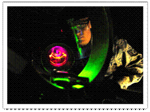
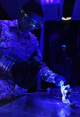
6. Dye Penetrant Inspection (DPI)
The dye penetrant inspection method is used to detect invisible surface defects in a nonmagnetic casting. The casting is brushed with, sprayed with, or dipped into a dye containing a fluorescent material. The surface to be inspected is the wiped, dried and viewed in darkness. The discontinuous in the surface will then be readily discernible.
7. Coin Testing
By hitting with coin on to the component and by hearing the sound coming from the casing, the presence of defect can be estimated.
we are really happy to inform you that our technical world successfully reach1.5 L Viewers so this is the right time to celebrate our happiness our technical team conduct a quiz you can participate without any cost, once you will select we will contact back and the award will distribute by team and certificate will be provided.
Rules and Regulations
1. only one time you can participate
2. your details we never collect and share if you won the quiz we will send the mail
3. Quiz team judgment is final.
4.quiz link is below attached must change your phone to desktop mode
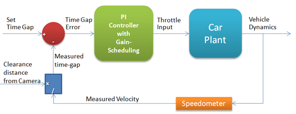
Adaptive Cruise Control (ACC) is an automotive feature that allows a vehicle’s cruise control system to adapt the vehicle speed to the environment. A radar system attached to the front of the vehicle is used to detect whether slower moving vehicles are in the ACC vehicle path. If a slower moving vehicle is detected, the ACC system will slow the vehicle down and control the clearance, or time gap, between the ACC vehicle and the forward vehicle. If the system detects that the forward vehicle is no longer in the ACC vehicle path, the ACC system will accelerate the back to its set cruise control speed. This operation allows the ACC vehicle to autonomously slow down and speed up is controlled is via engine throttle control and limited brake operation.
HOW DOES IT WORK?
The radar headway sensor sends information to a digital signal processor, which in turn translates the speed and distance information for a longitudinal controller. The result? If the lead vehicle slows down, or if another object is detected, the system sends a signal to the engine or braking system to decelerate. Then, when the road is clear, the system will re-accelerate the vehicle back to the set speed.
The adaptive cruise control (ACC) system depends on two infrared sensors to detect cars up ahead. Each sensor has an emitter, which sends out a beam of infrared light energy, and a receiver, which captures light reflected back from the vehicle ahead.
The first sensor, called the sweep long-range sensor, uses a narrow infrared beam to detect objects six to 50 yards away. At its widest point, the beam covers no more than the width of one highway lane, so this sensor detects only vehicles directly ahead and doesn’t detect cars in other lanes. Even so, it has to deal with some tricky situations, like keeping track of the right target when the car goes around a curve. To deal with that problem, the system has a solid-state gyro that instantaneously transmits curve-radius information to the sweep sensor, which steers its beam accordingly.
Another challenge arises when a car suddenly cuts in front of an ACC-equipped car. Because the sweep sensor’s beam is so narrow, it doesn’t “see” the other car until it’s smack in the middle of the lane. That’s where the other sensor, called the cut-in sensor, comes in. It has two wide beams that “look” into adjacent lanes, up to a distance of 30 yards ahead. And because it ignores anything that isn’t moving at least 30 percent as fast as the car in which it is mounted, highway signs and parked cars on the side of the road don’t confuse it.
Information from the sensors goes to the Vehicle Application Controller (VAC), the system’s computing and communication center. The VAC reads the settings the driver has selected and figures out such things as how fast the car should go to maintain the proper distance from cars ahead and when the car should release the throttle or downshift to slow down. Then it communicates that information to devices that control the engine and the transmission.
There are several inputs:
System on/off: If on, denotes that the cruise-control system should maintain the car speed.
Engine on/off: If on, denotes that the car engine is turned on; the cruise-control system is only active if the engine is on.
Pulses from wheel: A pulse is sent for every revolution of the wheel.
Accelerator: Indication of how far the accelerator has been pressed.
Brake: On when the brake is pressed; the cruise-control system temporarily reverts to manual control if the brake is pressed.
Increase/Decrease Speed: Increase or decrease the maintained speed; only applicable if the cruise-control system is on.
Resume: Resume the last maintained speed; only applicable if the cruise-control system is on.
Clock: Timing pulse every millisecond.
There is one output from the system:
Throttle: Digital value for the engineer throttle setting.
ADAPTIVE CRUISE CONTROL FEATURES
– Maintains a safe, comfortable distance between vehicles without driver interventions
– Maintains a consistent performance in poor visibility conditions.
– Maintains a continuous performance during road turns and elevation changes
– Alerts drivers by way of automatic braking.
PHYSICAL LAYOUT
The ACC system consists of a series of interconnecting components and systems. The method of communication between the different modules is via a serial communication network known as the Controller Area Network (CAN).
ACC Module – The primary function of the ACC module is to process the radar information and determine if a forward vehicle is present. When the ACC system is in ‘time gap control’, it sends information to the Engine Control and Brake Control modules to control the clearance between the ACC Vehicle and the Target Vehicle.
Engine Control Module – The primary function of the Engine Control Module is to receive information from the ACC module and Instrument Cluster and control the vehicle’s speed based on this information. The Engine Control Module controls vehicle speed by controlling the engine’s throttle.
Brake Control Module – The primary function of the Brake Control Module is to determine vehicle speed via each wheel and to decelerate the vehicle by applying the brakes when requested by the ACC Module. The braking system is hydraulic with electronic enhancement, such as an ABS brake system, and is not full authority brake by wire.
Instrument Cluster – The primary function of the Instrument Cluster is to process the Cruise Switches and send their information to the ACC and Engine Control Modules. The Instrument Cluster also displays text messages and telltales for the driver so that the driver has information regarding the state of the ACC system.
CAN – The Controller Area Network (CAN) is an automotive standard network that utilizes a 2 wire bus to transmit and receive data. Each node on the network has the capability to transmit 0 to 8 bytes of data in a message frame. A message frame consists of a message header, followed by 0 to 8 data bytes, and then a checksum. The message header is a unique identifier that determines the message priority. Any node on the network can transmit data if the bus is free. If multiple nodes attempt to transmit at the same time, an arbitration scheme is used to determine which node will control the bus. The message with the highest priority, as defined in its header, will win the arbitration and its message will be transmitted. The losing message will retry to send its message as soon as it detects a bus free state.
Cruise Switches – The Cruise Switches are mounted on the steering wheel and have several buttons which allow the driver to command operation of the ACC system. The switches include:
‘On’: place system in the ‘ACC standby’ state
‘Off”: cancel ACC operation and place system in the ‘ACC off’ state
‘Set +’: activate ACC and establish set speed or accelerate
‘Coast’: decelerate
‘Resume’: resume to set speed
‘Time Gap +’: increase gap
‘Time gap –’: decrease gap
ADVANTAGES
1. The driver is relieved from the task of careful acceleration, deceleration and braking in congested traffics.
2. A highly responsive traffic system that adjusts itself to avoid accidents can be developed.
3. Since the braking and acceleration are done in a systematic way, the fuel efficiency of the vehicle is increased.
DISADVANTAGES
1. A cheap version is not yet realized.
2. A high market penetration is required if a society of intelligent vehicles is to be formed.
3. Encourages the driver to become careless. It can lead to severe accidents if the system is malfunctioning.
4. The ACC systems yet evolved enable vehicles to cooperate with the other vehicles and hence do not respond directly to the traffic signals.

 #casting testing
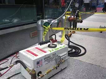

 The dye penetrant inspection method is used to detect invisible surface defects in a nonmagnetic casting. The casting is brushed with, sprayed with, or dipped into a dye containing a fluorescent material. The surface to be inspected is the wiped, dried and viewed in darkness. The discontinuous in the surface will then be readily discernible.