Monday, 30 April 2018

TURBO COMBUSTION ENGINE


TURBO COMBUSTION ENGINE
Image result for TURBO COMBUSTION ENGINE

Turbo combustion engine technology is that almost converting exhaust gas into a useful power. In this type of engine technology the fuel is compressed to a high extent and the expansion stroke is applied on the rotor.
            It is almost entirely different from the common IC engines, because here the four processes occur in every rotation. In a first half revolution, the suction and expansion processes are occurs and the second half of the revolution, the compression and exhaust processes are completed.
            So, long power stroke can be obtained in every single revolution.
            These Turbo Combustion engine can be made in single or multiple cylinders to suit variety of applications.


ADVANTAGES
Ø  Nearing 70% of fuel is saved.
Ø  It eco-friendly engine (i.e. petrol, diesel, biodiesel, gasoline, and Hydrogen).
Ø  Less vibration.
Ø  Friction is reduced.
Ø  Noise is reduced.
Ø Cam shaft is not required, though the cams are machined in the crank shaft.


labors day special


                           labors day special  Image result for தொழிலாலர் தின கவிதை


You are the wonders you sowed
This is a rocky ground
Pregnant woman alive!

You ... pluck the mud across the body
Who made this world ...
You are ...
Arttappattavana ...
Image result for தொழிலாலர் தின கவிதை
On the raised shoulder
Raising society ...
In the arms you raised
The Renaissance

Sweat your sweat ...
It will marry your country
Makarantattukalkal ...
Related image
Scars in your arms
It will grow to introduce the nation
Signs ....

If you did not lift
My palm
If you did not break the rocks
These are the axes of the earth
Life will be lost ...!

Do you know?
If you choose to rest
Stop the flow
This world ...

Image result for தொழிலாலர் தின கவிதை
In my view
Mother and you are the same
Mother is breaking the blood ...
You are .. sweating it ...

Leave to rest for labor
Dawn can not be found
Any nation ..
No man ...Image result for தொழிலாலர் தின கவிதை

My sweet sweat ..!
Shine on your forehead
Everything is sweating
My poem ....

Guys ....
Let's sweat the sweat
Then why tears


thank you google transulator  

RAPID PROTOTYPING


 RAPID PROTOTYPING


 Image result for RAPID PROTOTYPING
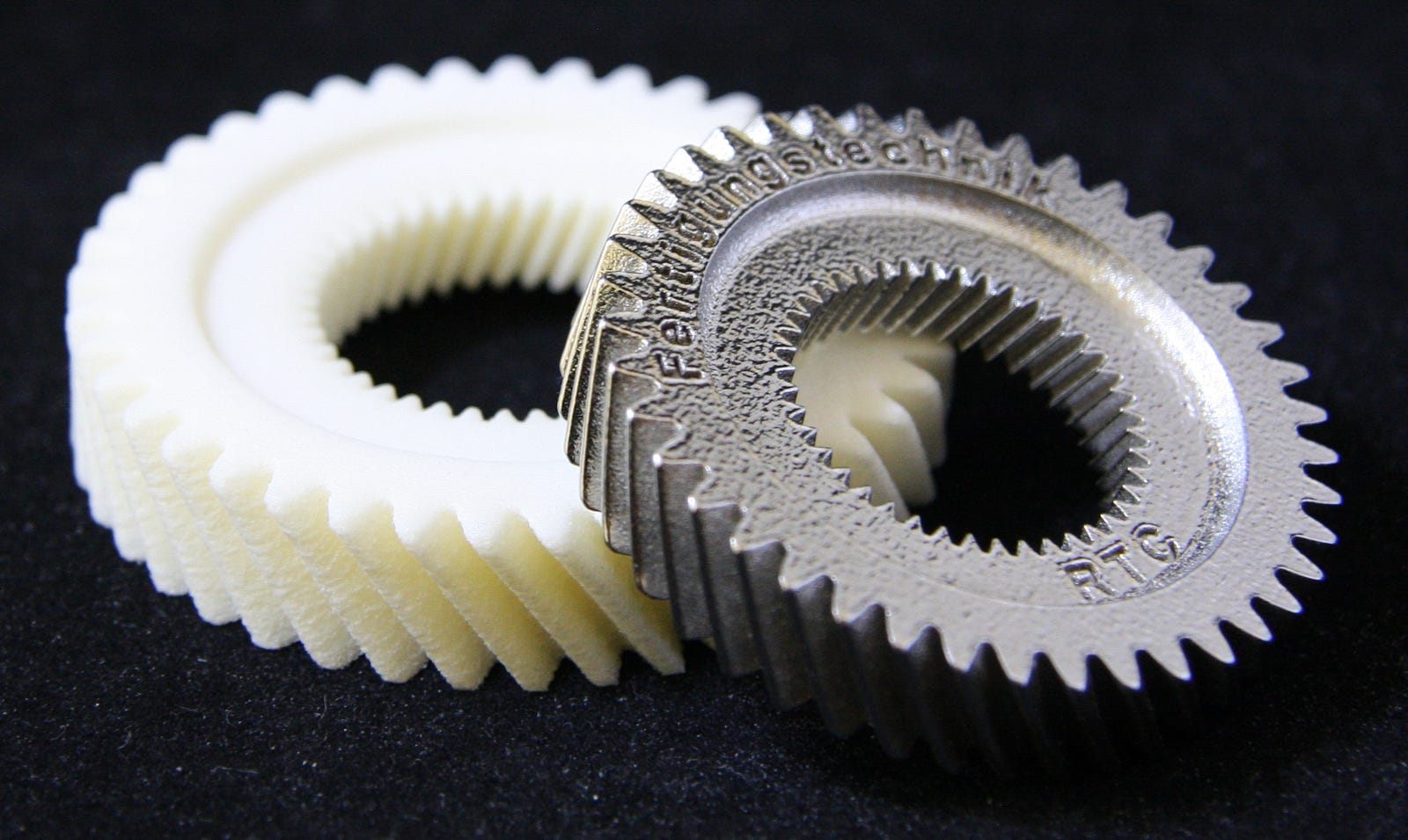
This paper deals with” RAPID PROTOTYPING” as in conventional machining process. Rapid prototyping refer to creation of three-dimensional objects directly from CAD files. And it is the automatic construction of physical objects using solid freeform fabrication. System of rapid prototyping to a set of processes in which the physical object is obtained directly from its cad model without explicitly going through the various steps of manufacturing which includes tooling and material removal. Rapid prototyping system using base materials are thermoplastics, metal powders, eutectic metals, photopolymer, titanium alloys and various materials. It advantages is offers direct manufacturing from cad files and sketches and paperless manufacturing, very past development of functional parts is possible, it offers greater capability to compute mass properties of components and assemblies.
 INDRODUCTION

              Rapid prototyping starts with quick creation of manufacturing ready, CAD models; continues to verify the design using CAE (computer aided engineering) tools.the first techniques for rapid prototyping became available in the late 1980s and were used to produce models and prototypes parts. Today, they are used for a much wider range of applications and are even used to manufacture production quality parts in relatively small numbers. Some sculptors use the technology to produce complex shapes for fine arts exihibition.In rapid prototyping,the machine reads in data from a CAD drawing and lays down successive layers of liquid, powder, or sheet material, and in this way builds up the model from a series of cross sections.


 Image result for RAPID PROTOTYPING

PROTOTYPING
Prototyping can resolve uncertainty about how well a design fits the user's needs. It helps designers to make decisions by obtaining information from users about the necessary functionality of the system, user help needs, a suitable sequence of operations, and the look of the interface.

PROTOTYPING METHODS

Various kinds of prototyping have been developed to obtain different kinds of information such as requirements animation, rapid, incremental, and evolutionary prototyping.
v Requirements animation, in most cases used to demonstrate functionally, is construed in the software prototype that can be assessed by users. 
v Rapid prototyping is a form of collecting information on requirements and on the adequacy of possible designs.
v Incremental prototyping enables large systems to be installed in phases to avoid delays between specification and delivery.
v Prototyping evolutionary considered to be the most involved form of prototyping, is a compromise between production and prototyping.
RA

Sunday, 29 April 2018

HIGH SPEED MACHINING USING CRYOGENICS

HIGH SPEED MACHINING USING CRYOGENICS
Image result for HIGH SPEED MACHINING USING CRYOGENICS

In conventional machining processes when we go for high speed excessive heat is generated during the chip formation process, which increases the temperature of cutting tool and accelerates tool wear. Conventionally cutting fluid is used to cool and lubricate cutting process. However conventional cooling process has inherent health and environmental problems .In addition to this a process should facilitate longer tool life ,higher cutting speed ,better work surface, less built up edge, easier chip breaking and lower production cost.

Image result for HIGH SPEED MACHINING USING CRYOGENICS
Cryogenic machining is one such process in which above mentioned features are present. Cryogenic machining uses Liquid Nitrogen (LN2) as a coolant. LN2 has a boiling point of -199 degree centigrade. It has been observed that at cryogenic temperatures tool materials get harder and stronger. A micro nozzle is formed between tool face and chip breaker and LN2 is passed through it. The chip breaker helps to lift chip so that the jet reaches the hottest spot i.e. tool chip interface. At this point LN2 absorbs heat and evaporates producing gas cushion causing lubrication effect. This localized cryogenic cooling reduces the tool face temperature, enhances its hardness, so less wear rate .The lubrication effect reduces friction and tool wear.
This new cryogenic machining eliminates the built up edge (BUE) problem on tools because cold temperature reduces possibility of chips welding to tool. So the process will allow high speed cutting without built up edge. In addition to various advantages of the cryogenic machining, the paper discloses the comparison of cryogenic machining with conventional process in the aspects of tool life, productivity, and production cost


Image result for HIGH SPEED MACHINING USING CRYOGENICS


GREEN COMPOSITES- BY MOSES DHILIP KUMAR

                                      GREEN COMPOSITES-
Image result for GREEN COMPOSITES-

                             Currently, most plastics are simply buried in landfills where they remain for thousands of years.  Fiber-reinforced composites have been used for many applications from sporting goods to automotive parts. Most commercial fiber-reinforced composites are made from petroleum based synthetic fibers and resins that are non-degradable. Waste disposal problems and rising petroleum prices necessitate that some of the dependency on plastics be shifted to new materials. Using plant-based short and continuous cellulosic fibers in soy-protein polymer resin, that is fully-degradable, environment-friendly, 'Green' composites. Green composites can be made by the combination of Bio-degradable Resin and Natural Fibers.
Image result for GREEN COMPOSITES-
 The random short fiber composites have moderate mechanical properties and can be used in non-structural applications. The unidirectional continuous fiber composites have tensile properties close to steel. However, at a typical steel-to-composite density ratio of about 6, these green composites are significantly superior to steel on a per weight basis and used for indoor structural applications in housing, transportation and automobiles. In recent years there has been considerable interest in using natural plant fibers as reinforcements for plastics. The motivation includes cost, performance enhancement, weight reduction, and environment concerns. High performance flax fiber could be a substitute for glass or carbon fibers as reinforcements for plastics.

FROM PINEAPPLE FIBERS AND POLY (HYDROXYBUTYRATE-CO-VALERATE) RESIN
                            Tensile properties of pineapple fibers, like most natural fibers, show a large variation. The average interfacial shear strength between the pineapple fiber and poly (hydroxybutyrate-co-valerate) (PHBV) is about 8.23 MPa, Fully degradable and environment-friendly Green Composites are made by combining pineapple fibers and PHBV with 20 and 30% weight content of fibers placed in a 0°/90°/0 ° fiber arrangements. Even though tensile and flexural strength and moduli of these green composites are lower than those of some wood specimens tested in grain direction, but they are significantly higher in perpendicular to grain direction. Compared to PHBV virgin resin, both tensile and flexural strength and moduli of these green composites were significantly higher. SEM photomicrographs of the fracture surface of the green composites, in tensile mode, showed partial fiber pull-out indicating weak bonding between the fiber and the matrix.

FROM RECYCLED CELLULOSE AND POLY (LACTIC ACID)
                        Green Composites were prepared from poly (lactic acid) (PLA) and recycled cellulose fibers (from newsprint) by extrusion followed by injection molding processing. Compared to the neat resin, the tensile and flexural moduli of the green composites are significantly higher. This is due to higher modulus of the reinforcement added to the PLA matrix. Differential scanning calorimetry (DSC) and Thermo gravimetric analysis (TGA) show that the presence of cellulose fibers do not significantly affect the crystallinity, or the thermal decomposition of PLA matrix up to 30 wt% cellulose fiber content. Overall it was concluded that recycled cellulose fibers from newsprint could be a potential reinforcement for the high performance biodegradable polymer green composites

FROM RECYCLED CELLULOSE FIBER AND POLY (3-HYDROXYBUTYRATE-CO-3-HYDROXYVALERATE) BIOPLASTIC
                        Green composites are successfully fabricated from recycled cellulose fibers and bacterial polyester, poly (3-hydroxybutyrate-co-3-hydroxyvalerate) (PHBV) by melt mixing techniques. Various weight contents (15%, 30%, and 40%) of the fibers were incorporated in the PHBV matrix. The tensile and storage moduli of the PHBV-based composites improves by 220% and 190%, respectively, by reinforcement with 40 wt % RCF and the heat deflection temperature (HDT) increases from 105 to 131 C, while the coefficient of linear thermal expansion (CLTE) value reduces by 70% upon reinforcement with 40 wt % RCF. The PHBV-based composites had also shown better tensile and storage moduli and lower CLTE values than PP-based composites.Image result for GREEN COMPOSITES-


AUTOMATIC HIGHWAY ANTI-COLLIDING SYSTEM by moses dhilip kumAR


                AUTOMATIC HIGHWAY
      ANTI-COLLIDING SYSTEM
ABSTRACT:

                       We are living in an automobile society, and as far as this field is concerned the accidents are the main problems that have to be solved. In Chennai alone nearly 1900 fatal road accidents have taken place in 2005 which nearly claimed 1800 precious lives.
                                Driver’s assistance system plays a major role in cars since it minimizes the risk and consequences of accidents and increases the driving comfort level. Highway anti-colliding system is intended to provide drivers with brake assistance to avoid front end collision. On highways, if the principle other vehicle (POV) suddenly stops, then the host vehicle will collide it resulting in an accident. Due to less reaction time and loss of presence of mind, driver can’t stop the vehicle through brake.
              The aim of this paper is to stop the vehicle at such circumstances and this paper gives an outline of whole system and constructional features of each component and working principle. Adaptations of the system in the future automobiles have also been considered. Related image

WORKING PRINCIPLE:


·       The principle of ultrasonic detection is based on measuring the time taken between transmission of an ultrasonic wave (pressure wave) and reception of its echo (return of transmitted wave). The distance range is 6-10 m.

·       The relay opens or closes its switch contacts in some prearranged and fixed combination. The contacts may be in the same circuit or a combination of circuit or in another circuit.

·       When a current is passed through the solenoid the slug is attracted towards the centre of the coil with a force determined by the current in the coil. The motion of the slug may be opposed by a spring to produce a displacement output, or the slug may simply free to move.


·       Torque is produced by interaction between the axial current carrying rotor conductors and the magnetic flux produced by the permanent magnets. The only way to control its speed is to vary the armature voltage with the help of an armature rheostat.

Related imageTHANK YOU ALL  STAY WITH US